Understand complex hydrogeological systems with SEEP/W and SEEP3D
Model groundwater flow for geotechnical and environmental problems subject to a variety of boundary conditions
Go to storeTry it nowUnlock deep insights into complex groundwater problems for civil, mining infrastructure, and waste cover design projects.
Plan complex geo-engineering projects with confidence, like dams, wells, tunnels, bridges, and mines.
Ensure safety and compliance by incorporating critical data into planning and design.
Overcome complexity and risk in design
Understand the flow dynamics of complex hydrogeological systems to mitigate risk for your geo-engineering and earth science projects.
Examine static and dynamic influences on groundwater conditions and anticipate future risks to storage and systems.
Optimise engineering and construction solutions
Design the safest and most cost-effective solutions for high-risk engineering projects such as mine dewatering systems, civil infrastructure construction, tailings dams and more.
Use built-in hydraulic functions to easily estimate volumetric water content and conductivity with limited input.
Analyse extreme conditions and scenarios
Analyse extreme conditions such as flood events, rapid drawdown, and the effect of severe climate events on groundwater conditions and design performance.
Integrate data from other applications to factor in extreme weather and analyse density dependency for frozen ground and water movement.
SEEP/W and SEEP3D are part of GeoStudio integrated geo-engineering software.
SEEP/W Stories

GeoStudio Answer Hour: New Features in GeoStudio
GeoStudio 2024.1 continues to build on Seequent’s geotechnical analysis solution, with the addition of many…

Integrate, communicate, and interpret geotechnical data
with industry-leading geo-engineering numerical modelling
Try it nowKey features

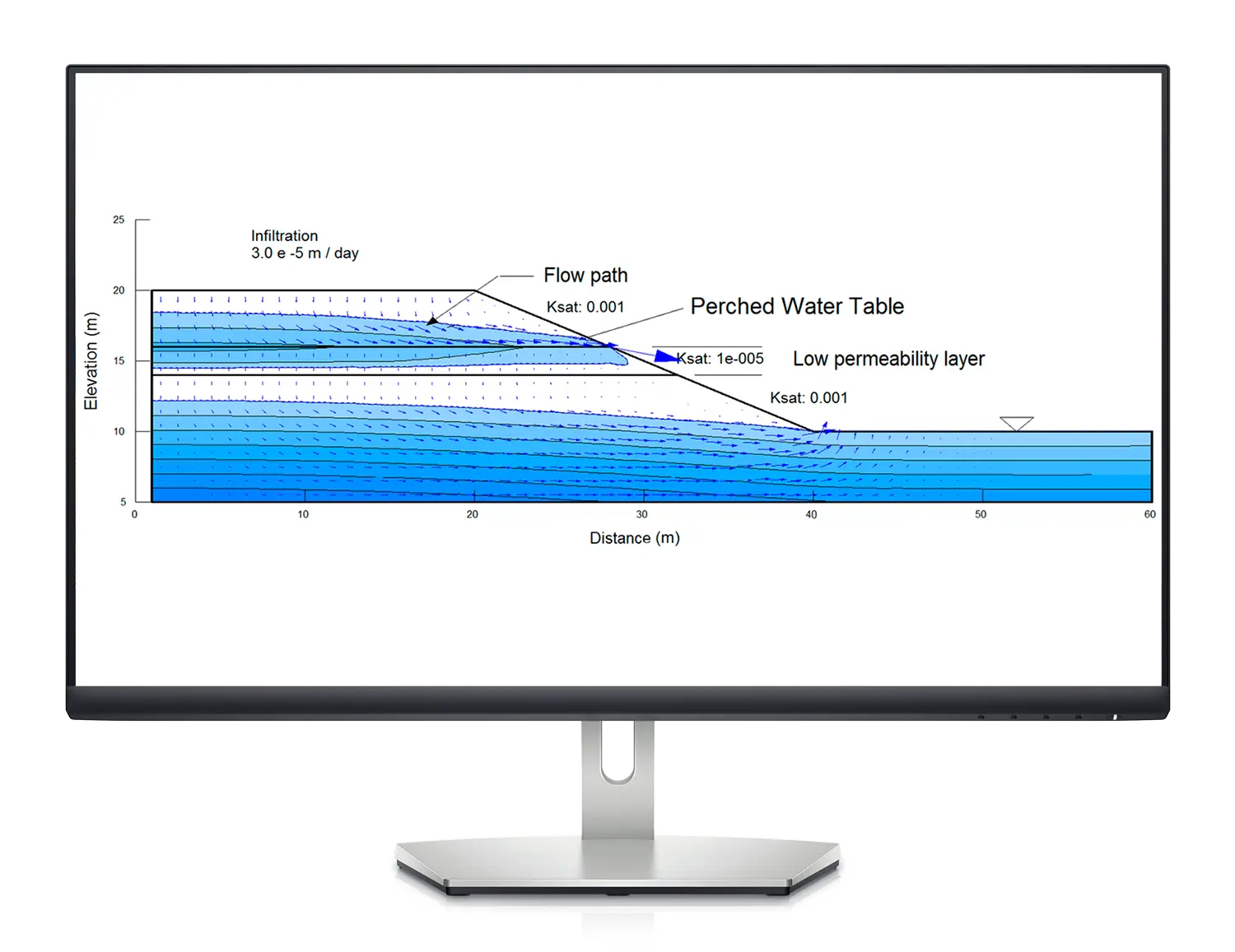
Explore multiple boundary condition options
Input field data or functional relationships to define hydrographs, reservoir fluctuations, rainfall cycles, vegetation effects, or land-climate interactions.

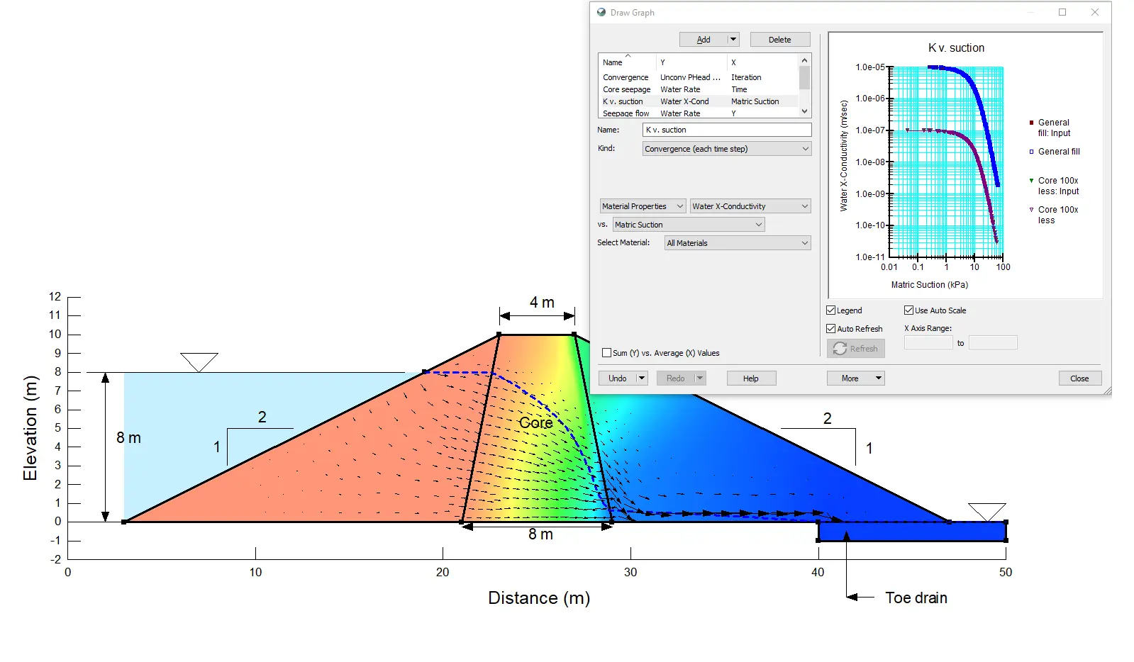
Integrate SLOPE/W for a deeper picture
Combine SLOPE/W and SEEP3D or SEEP/W to analyse the stability of any system subject to changes in pore-water pressure then seamlessly analyse 2D and 3D groundwater flow.

Examine materials and pore-water storage
Rapidly estimate hydraulic conductivity and volumetric water content functions using an built-in estimation tools to analyse both saturated and unsaturated conditions.
Apply rigorous formulas to analyse flow
Use the saturated/unsaturated formulation to analyse the most demanding flow problems, such as infiltration into dry soil or seepage through complex upstream tailings dams.

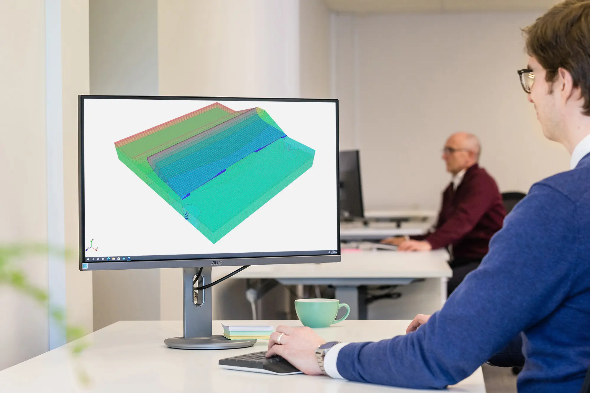
Tackle simple and complex problems
Model simple saturated steady-state problems or sophisticated saturated/unsaturated transient analyses with atmospheric coupling at the ground surface.
Useful Information
System Requirements
We recommend you use Windows 10, with a reasonably fast processor, mid range graphics and 32GB of system memory.
Supported Data/Formats
Supported kinds of data and formats that you can use with Leapfrog Geo.